Quantcast
Channel: Eurocircuits
Viewing all 617 articles
Browse latest View live

Students of Université Catholique de Louvain competing in the EUROBOT competition.

$
0
0

UCL students competing in EUROBOT – Eurocircuits PCBs inside the BOTs.

THEIR STORY

We are a group of 28 students from the Université Catholique de Louvain, and we are currently following a Master’s in mechatronics.

Our study program includes an important project, which is to participate to an international robotic contest named Eurobot. In this contest, teams have to design and construct a small autonomous robot that can perform several actions, such as manipulating blocks and sorting them by color, or shooting ping-pong balls in a basket.

Although there are several specifications to fulfil (e.g., regarding the size of the robot or restrictions regarding its components), we also have a lot of freedom regarding the mechanisms embedded in the robot. Therefore, Eurobot is a nice opportunity to train our engineering skills in design and programming.

UCL1

UCL2

We formed 5 teams of 5 to 6 students, and each team designed an original robot to take part in the contest.

Some of them are visible here.

Because the robot has to be autonomous, it contains many electrical parts.

There are actuators and sensors to perform the actions, CPUs to supervise them, and batteries.

We have designed specific electronic circuits to link these elements together.

Eurocircuits, gold sponsor of this project, played a key role in the manufacturing of the PCBs.

You can see the nice realization of these PCBs below.

UCL3

UCL4

UCL5

UCL6

After the mechanical and electrical assembly of the robot, we proceeded to a long phase of tests and improvements.

The day of the Belgian competition finally arrived. Our work has been rewarded since one of our team became Vice-champion and got qualified for the European finals, held in France. Although very challenging, they managed to reach there the fourth place of the leaderboard!

Of course, the design of our robots was not perfect, but we have learnt a lot during this project. Creating a robot from scratch was an amazing experience and we will definitely recommend this study program to others.

Naturally, this project would not have been possible without the support of the teaching staff and the gold sponsors, including Eurocircuits.

You want to know more about our achievements? Watch our video stories here.

Center for Research in Mechatronics
Institute of Mechanics, Materials, and Civil Engineering
Place du Levant, 2 bte L5.04.02 B-1348 Louvain-la-Neuve

Be the first to read all about our news and novelties.  linkedin-logo google-plus-icon fb-logo Twitter_Icon youtube-logo-full-color


Insight Technology – The Double-Sided Production Flow

$
0
0
PCB Services | eC Solutions
Insight Technology – The Double-Sided Production Flow

Double Sided PCB production sounds simple enough, but have you ever wondered what the actual production flow involves.

Using our Eurocircuits Insight Technology platform we have made a short informative video that explains the process flow.

There are more than 20 process steps required to make a Double-Sided PCB. It all starts with the selection of the material. This consists of a base material that is covered with copper foil on one or both sides.

The type of base material selected, depends on the function and design of the PCB, it may be an FR4 or Ceramic or Aluminium based material. In addition the selection depends on the required Isolation, Cu Thickness and the Tg value etc.

Once the base material is selected then the production process begins, why not take a few minutes to watch our informative video present by Gruber András, our Production Coordinator.

Should you have any questions about any of our services, please feel free to get in touch via email, telephone or instantly with our online chat during office hours. We will be more than happy to help.

Why not follow us on our social media, keeping up to date with all of our latest news?


News & Information

For many years Eurocircuits have provided you with important News & Information about our services, products, free to use smart tools and the Electronic Manufacturing World. Take a peak at what we offer:

  Eurocircuits company update. This section contains updates and information about the Eurocircuits Group. As a valued partner you will receive updates and news covering our company activities, team news and business developments etc.

  Events & Workshops. Eurocircuits is an active participant of events and exhibitions, it also organises events, seminars and workshops, especially concerning technical topics

  Tips & Tricks.The electronic value chain starts with a design and then converting it to a digital form. This section covers all design related issues, their influence on manufacturing.

  Electronic Manufacturing Technology. Eurocircuits goal is to inform all Electronic Designers about Electronic Manufacturing Techniques and processes. Whilst, this may start with PCB manufacturing it also covers the Assembly, Testing and Housing etc…

  Online Smart Tools – Services & Products. All Eurocircuits customers have access to an online customer account and through this, access to our Smart Tools and services. This section covers User Guides, updates and new features and tools etc. It will help you to optimise your knowledge, use of these tools and the electronic manufacturing services and products we offer.

  Customer Applications & Student Projects. Eurocircuits actively encourages its customers to share their experiences with other customers. In addition to this, we support many student projects and inspire them to write about their adventures and the technology they have designed.

  eCvelo. Next to being an Electronics Manufacturing Company, Eurocircuits also has a heart for clean mobility. As result we have developed and are building trike and quad cycles with a covered frame. Keep updated by opting in to this section.

Eurocircuits TV

Eurocircuits TV is Eurocircuits’ media channel bringing electronic designers and others video news and VLOGs about our electronic manufacturing world.
Interact with us

The best way to share ideas and knowledge is face to face. Check out our eC-calendar

WoTS Proximo gadget – Be quick to reserve one!

$
0
0
PCB Services | eC Solutions

WoTS-gadget PROXIMO – be quick to reserve one

This year at the World of Electronics, one of the 5 worlds present at World of Technology & Science, you can participate in the PROXIMO project.

PROXIMO is a proximity sensor linked to a smart phone which results into a proximity application to be used during the exhibition but with various possibilities after the exhibition as well. The gadget is based on the Nordic 5.0 Bluetooth Low Energy chip. Eurocircuits customer IDEETRON is the developer of the electronics and Hogeschool Arnhem Nijmegen programs the app for the smart phone.

The only procedure to obtain the PROXIMO is to register for the exhibition World of Electronics and to physically collect the gadget at the exhibition.

Do Register Free here and collect your PROXIMO in Utrecht from the 2nd of October till the 5th.

Eurocircuits TV has made a short introduction movie for the Proximo project (Dutch spoken).

Eurocircuits TV also made movies of every step of the creation process of the PROXIMO. VLOGs click here.

You can find Eurocircuits at the World of Electronics on Booth 11F030. Come and say hello and let us tell you all about Eurocircuits, our PCB and PCBA services and many free to use powerful tools. The Eurocircuits online customer suit offers you the best guarantee to receive your Printed Circuit Board Assembled prototype or small series, “right first time” and in time and within budget.

The Eurocircuits Team will be happy to meet you there.


WoTS Proximo gadget – reserveer snel uw exemplaar!

$
0
0
PCB Services | eC Solutions

WoTS-gadget PROXIMO – reserveer snel uw exemplaar !

Dit jaar tijdens de World of Electronics, een van de 5 werelden van de beurs World of Technology & Science, kan u deelnemen aan het PROXIMO project.

PROXIMO is een nabijheidssensor gelinked aan een smart phone. Hierdoor ontstaat een applicatie die apparaten in de nabijheid kan waarnemen waardoor de PROXIMO bezitter tijdens de beurs verschillende toepassingen van het gadget kan gebruiken. Het hart van het gadget is de Nordic 5.0 Bluetooth Low Energy chip. Eurocircuits’ klant IDEETRON is de ontwikkelaar van het gadget en studenten van de Hogeschool Arnhem Nijmegen programmeerden de app voor de smart phone.

De enige manier om de PROXIMO te verwerven, is door te registeren voor de beurs, World of Electronics, en door uw gadget persoonlijk te komen ophalen tijdens de beurs.

Registeer nu gratis hier en haal uw PROXIMO af in Utrecht van 2 tem 5 oktober 2018.

Eurocircuits TV heeft een korte introductie film over het Proximo project gemaakt.

Eurocircuits TV maakte ook reportages over elke stap in het creatieproces van de PROXIMO. VLOGs klik hier.

U vindt Eurocircuits tijdens de World of Electronics in Stand 11F030. Bezoek ons en laat u inlichten over Eurocircuits, onze PCB en PCBA services en onze vele gratis te gebruiken slimme online tools. Het gebruik van de Eurocircuits online visualisatie en DFM tools is de beste garantie om uw Printed Circuit Board Assembled prototype of kleine serie, “right first time”, op tijd en binnen budget te verkrijgen.

Het Eurocircuits Team kijkt er naar uit om u in Utrecht te ontmoeten.


TU Delft Hyperloop team explains the PCBs in their POD

$
0
0

Delft Hyperloop is a student team of 37 students from the Technical University of Delft.

We spent a full-time year on the design and production of the hyperloop pod, ATLAS 01. With this pod, we participated in the third SpaceX Hyperloop Pod Competition 2018 in Los Angeles, California.

Delft Hyperloop also participated in the first hyperloop pod competition and won this competition with the highest score on the sum of all categories.

The competition of this year was a little bit different. The only goal of this year was: top speed!

This also meant that every pod needed to have his own energy source and propulsion system. We decided to go for a high voltage battery and an electromotor.

The high voltage battery is designed and built in-house. The battery consists of a 180S4P lithium polymer battery. This battery is designed to be able to deliver 200kW of power at a maximum voltage of 750VDC.

Because this battery consists of a lot of dangerous batteries, a battery management system (BMS) was needed to keep everything safe and under control.

This year, the choice was made to go for an off-the-shelf BMS because there was already a lot to design. This off-the-shelf BMS is there to:

  • Measure the temperature of every battery cell
  • Measure the voltage of every battery cell
  • Measure the output current of the battery pack
  • Control the high- and low to chassis contactors
  • Control the pre-charge circuit

The BMS consists of a BMS-master and BMS-slaves. The master talks to the slaves over CAN to get the voltage and temperature of every cell. The PCB that holds the slave modules is produced by Eurocircuits. This PCB made the battery modules look organized and kept the measurement wires towards the battery cell tabs short. Below you can see some photographs of the boards.

After a lot of work, the 20 best teams from all over the world were selected to the competition week from the 15th till the 22nd of July.

With that last week, all the work came together in one final run, and we ended 2nd in the SpaceX Hyperloop Pod competition of 2018!

Sjors Verkamman

PS. Also read our previous BLOG (Dutch)

Be the first to read all about our news and novelties.  linkedin-logo google-plus-icon fb-logo Twitter_Icon youtube-logo-full-color

TechAward World of Electronics – stem voor PCBA Visualizer

$
0
0
PCB Services | eC Solutions

TechAward World of Electronics – stem voor PCBA Visualizer !

Eurocircuits maakt fantastische “smart tools” die u als klant gratis kan gebruiken. Druk uw waardering uit voor onze investering en STEM voor PCBA Visualizer in de TechAward competitie van de World of Electronics beurs. Doe het nu want STEMMEN kan maar tot 1 september aanstaande.

Wil je meer weten over PCBA Visualizer en waarom wij dit een echte innovatie vinden kan u onderstaande film bekijken en de volgende pagina op de WoTS website.

Eurocircuits TV heeft een korte introductie film gemaakt over hoe PCBA Visualizer bijdraagt tot het produceren van uw bestukte PCB, prototype of kleine serie, “right first time“. De eerste keer goed.

Eurocircuits TV maakte ook reportages over elke stap in het creatieproces van de PROXIMO, het beursgadget voor de World of Electronics. VLOGs klik hier.

De enige manier om de PROXIMO te verwerven, is door te registeren voor de beurs, World of Electronics, en door uw gadget persoonlijk te komen ophalen tijdens de beurs.

Registeer nu gratis hier en haal uw PROXIMO af in Utrecht van 2 tem 5 oktober 2018.

U vindt Eurocircuits tijdens de World of Electronics in Stand 11F030. Bezoek ons en laat u inlichten over Eurocircuits, onze PCB en PCBA services en onze vele gratis te gebruiken slimme online tools. Het gebruik van de Eurocircuits online visualisatie en DFM tools is de beste garantie om uw Printed Circuit Board Assembled prototype of kleine serie, “right first time”, op tijd en binnen budget te verkrijgen.

Het Eurocircuits Team kijkt er naar uit om u in Utrecht te ontmoeten.


TechAward World of Electronics – vote for PCBA Visualizer

$
0
0
PCB Services | eC Solutions

TechAward World of Electronics – vote for PCBA Visualizer !

Eurocircuits creates fantastic “smart toolsfree to use by you our customer. Show your appreciation for our investment and VOTE for PCBA Visualizer in the TechAward competition of the World of Electronics exhibition. Do it now since VOTING is only possible till September 1st.

Do you wish to know more about PCBA Visualizer and why we believe that this is a real innovation? View the movie below and read the information on this page on the WoTS website.

Eurocircuits TV made a short movie on how PCBA Visualizer contributes to manufacturing your assembled PCB, prototype or small series, “right first time“.

Eurocircuits TV also made movies of every step of the creation process of the PROXIMO exhibition gadget of the World of Electronics. VLOGs click here.

The only procedure to obtain the PROXIMO is to register for the exhibition World of Electronics and to physically collect the gadget at the exhibition.

Do Register Free here and collect your PROXIMO in Utrecht from the 2nd of October till the 5th.

You can find Eurocircuits at the World of Electronics on Booth 11F030. Come and say hello and let us tell you all about Eurocircuits, our PCB and PCBA services and many free to use powerful tools. The Eurocircuits online customer suit offers you the best guarantee to receive your Printed Circuit Board Assembled prototype or small series, “right first time” and in time and within budget.

The Eurocircuits Team will be happy to meet you there.


Innovation through learning

$
0
0
PCB Services | eC Solutions
Innovation through learning

For more than 15 years Eurocircuits has supported European Electronic Engineering students, helping to complete innovative projects.

These projects cover many different topics including Rocket Engineering, Telemetry, Electric powered Racing Cars and Exoskeletons.

Our goal is to support and develop “Innovation Through Learning” by continuing to technically support students and their projects. To financially support the teams, we buy publicity of them which give us a nice exposure as well.

Please take a few minutes to review the projects we have been involved with, simple click on the picture below:

If you wish to have more details about our support criteria please follow the click here.

Should you have any questions about any of our services, please feel free to get in touch via email, telephone or instantly with our online chat during office hours. We will be more than happy to help.

Why not follow us on our social media, keeping up to date with all of our latest news?


News & Information

For many years Eurocircuits have provided you with important News & Information about our services, products, free to use smart tools and the Electronic Manufacturing World. Take a peak at what we offer:

  Eurocircuits company update. This section contains updates and information about the Eurocircuits Group. As a valued partner you will receive updates and news covering our company activities, team news and business developments etc.

  Events & Workshops. Eurocircuits is an active participant of events and exhibitions, it also organises events, seminars and workshops, especially concerning technical topics

  Tips & Tricks.The electronic value chain starts with a design and then converting it to a digital form. This section covers all design related issues, their influence on manufacturing.

  Electronic Manufacturing Technology. Eurocircuits goal is to inform all Electronic Designers about Electronic Manufacturing Techniques and processes. Whilst, this may start with PCB manufacturing it also covers the Assembly, Testing and Housing etc…

  Online Smart Tools – Services & Products. All Eurocircuits customers have access to an online customer account and through this, access to our Smart Tools and services. This section covers User Guides, updates and new features and tools etc. It will help you to optimise your knowledge, use of these tools and the electronic manufacturing services and products we offer.

  Customer Applications & Student Projects. Eurocircuits actively encourages its customers to share their experiences with other customers. In addition to this, we support many student projects and inspire them to write about their adventures and the technology they have designed.

  eCvelo. Next to being an Electronics Manufacturing Company, Eurocircuits also has a heart for clean mobility. As result we have developed and are building trike and quad cycles with a covered frame. Keep updated by opting in to this section.

Eurocircuits TV

Eurocircuits TV is Eurocircuits’ media channel bringing electronic designers and others video news and VLOGs about our electronic manufacturing world.


PROXIMO het WoTS-gadget – Laatste exemplaren! – Reserveer nu!

$
0
0
PCB Services | eC Solutions

PROXIMO het WoTS-gadget – Laatste exemplaren! – Reserveer nu!

Wees er snel bij want de PROXIMO gadgets zijn bijna op. De enige manier om de PROXIMO te verwerven, is door te registeren voor de beurs, World of Electronics, en door uw gadget persoonlijk op te halen tijdens de beurs.

Registeer hier nu gratis en haal uw PROXIMO af in Utrecht !

PROXIMO is een nabijheidssensor gelinked aan een smart phone. Hierdoor ontstaat een applicatie die apparaten in de nabijheid kan waarnemen waardoor de PROXIMO bezitter tijdens de beurs verschillende toepassingen van het gadget kan gebruiken. Het hart van het gadget is de Nordic 5.0 Bluetooth Low Energy chip. Eurocircuits’ klant IDEETRON is de ontwikkelaar van het gadget en studenten van de Hogeschool Arnhem Nijmegen programmeerden de app voor de smart phone.

Eurocircuits TV heeft een korte introductie film over het Proximo project gemaakt.

Eurocircuits TV maakte ook reportages over elke stap in het creatieproces van de PROXIMO. VLOGs klik hier.

U vindt Eurocircuits tijdens de World of Electronics van 2 tem 5 oktober 2018 op Stand 11F030. Bezoek ons en laat u inlichten over Eurocircuits, onze PCB en PCBA services en onze vele gratis te gebruiken slimme online tools. Het gebruik van de Eurocircuits online visualisatie en DFM tools is de beste garantie om uw Printed Circuit Board Assembled prototype of kleine serie, “right first time“, op tijd en binnen budget te verkrijgen.

Het Eurocircuits Team kijkt er naar uit om u in Utrecht te ontmoeten.


PROXIMO the WoTS-gadget – Last pieces! – Reserve now!

$
0
0
PCB Services | eC Solutions

PROXIMO the WoTS-gadget – Last pieces! – Reserve now!

Be quick as all PROXIMO gadgets are almost reserved. The only procedure to obtain the PROXIMO is to register for the exhibition World of Electronics and to physically collect the gadget at the exhibition.

Register Free Now and collect your PROXIMO in Utrecht !

PROXIMO is a proximity sensor linked to a smart phone which results into a proximity application to be used during the exhibition but with various possibilities after the exhibition as well. The gadget is based on the Nordic 5.0 Bluetooth Low Energy chip. Eurocircuits customer IDEETRON is the developer of the electronics and Hogeschool Arnhem Nijmegen programs the app for the smart phone.

Eurocircuits TV has made a short introduction movie for the Proximo project (Dutch spoken).

Eurocircuits TV also made movies of every step of the creation process of the PROXIMO. VLOGs click here.

You can find Eurocircuits at the World of Electronics from the 2nd of October till the 5th on Booth 11F030. Come and say hello and let us tell you all about Eurocircuits, our PCB and PCBA services and many free to use powerful tools. The Eurocircuits online customer suit offers you the best guarantee to receive your Printed Circuit Board Assembled prototype or small series, “right first time” and in time and within budget.

The Eurocircuits Team will be happy to meet you there.


Press Release September 2018 – Right First Time with PCBA Visualizer

$
0
0

Right First Time with PCBA Visualizer

Eurocircuits has now added the PCBA Visualizerto their online eC Smart Tools seamlessly linking PCB Manufacture to PCB Assembly and driving their philosophy of “Right First Time for Manufacture”.

It is without a doubt that the PCBA Visualizer brings unparcelled functionality and control to the customer. It allows them to visually check that the selected components physically fit their PCB layout before the manufacturing process starts, thus avoiding lengthy delays or costly remakes.

Background

To support their philosophy of “Right First Time for Manufacture” Eurocircuits has two approaches. The first is to provide information via their website to help Design Engineers understand the manufacturing process. Secondly, to provide online eC Smart Tools to help check design data before it goes to manufacture.

Eurocircuits developed the PCB Visualizer some years ago and have continued to enhance the features ever since. This was the first of their online eC Smart Tools allowing customers to upload their bare PCB board data and visually check and repair any issues related to manufacturing.

The PCB Visualizer helped reduce the data anomalies before manufacturing from 25% to less than 3% thus representing a serious WIN-WIN between customer and manufacturer.

Present

In late 2017 Eurocircuits entered the PCB Assembly arena to offer their customers a One Stop Shop for their Prototype and Small Series PCB requirements and introduced the PCBA Visualizer (the ‘A’ standing for Assembly).

This online eC Smart Tool allows customers to upload their BOM (Bill of Materials) and CPL (Component Placement List) data where it is automatically analysed, parts identified and location on the actual PCB defined.

The PCBA Visualizer helps to resolve issues such as correcting component rotation/alignment, assigning polarity, selecting alternative parts along with many others. The goal is, as it always is with Eurocircuits, to have data that is “Right First Time for Manufacture”.

With the PCBA Visualizer the Eurocircuits customer will ultimately have PCB design, BOM and CPL data that has been validated for manufacture, there is even a 3D graphical representation of the assembled product available.

Therefore, the number of errors prior to the actual production can be drastically reduced or even eliminated. As a result, the process is more efficient, making these smaller orders more cost effective, hence the creation of a new market: assembly of prototypes and small series as a business.

Video:

The PCB Visualizer and PCBA Visualizer along with the eC Smart Tools help Electronic Designers to identify PCB and Assembly manufacturing issues before they place their order. These Powerful Tools are free to use for Eurocircuits customers, thus optimising their PCB design flow and ensuring “Right First Time for Manufacture”.

(embed code for this video – <iframe width=”640″ height=”564″ src=”https://player.vimeo.com/video/269569379″ frameborder=”0″ allowFullScreen mozallowfullscreen webkitAllowFullScreen></iframe>)

For more information visit the Eurocircuits website www.eurocircuits.com.

About Eurocircuits

Founded in 1991, Eurocircuits is a Belgian group specializing in the manufacturing and online distribution of Bare and Assembled Circuit Board Prototypes and Small Series from its own production facilities in Germany, India, and Hungary. For almost 30 years now, our continuously further developed, integrated, web-based business model offers customers a broad range of technologies that are fast, reliable, and cost-effective. In 2017 we delivered over 107,000 orders to over 12,000 customers mainly in Europe – over 98% of them on time.

Video:

In 80 seconds this video tells you all the high lights about Eurocircuits. More info can be found on the Eurocircuits website, eurocircuits.comand their online TV channel eurocircuits.tv

(Embed code for this video – <iframe width=”640″ height=”564″ src=”https://player.vimeo.com/video/287447538″ frameborder=”0″ allowFullScreen mozallowfullscreen webkitAllowFullScreen></iframe>)

Meet Eurocircuits

During the Fall of 2018, Eurocircuits’ teams will bring the above message to the market on the occasions:

  • TEC Lund – Lund Sweden – 27 September
  • World of Technology @ Science – Utrecht The Netherlands – 2-5 October
  • Engineering Design Show – Coventry UK – 17-18 October
  • Prototyping 2018 – Kortrijk Belgium – 7-8 November
  • D&E event – Mechelen Belgium – 7 November
  • D&E event – Den Bosch The Netherlands – 8 November
  • MATELEC – Madrid Spain – 13-16 November
  • Electronica – Munich Germany – 13-16 November
  • LED event – Mechelen Belgium – 28 November
  • LED event – Den Bosch The Netherlands – 29 November

Do you wish more information, please contact,

Dirk Stans
Eurocircuits NV
Managing partner, Sales & marketing
Antwerpsesteenweg 66, 2800 Mechelen, Belgium
Dirk.Stans@eurocircuits.com
www.eurocircuits.com

Project March III – Students of the Delft University of Technology present a new exoskeleton!

$
0
0

New exoskeleton: one step closer to independent walking for people with a spinal cord injury.

On 14th of august 2018, students from Project MARCH presented a new and improved exoskeleton for people with a spinal cord injury, the MARCH III. Sjaan Quirijns, who has a spinal cord injury since 2000, revealed the exoskeleton by walking up the stage and demonstrating the motor harness. The improvements in the new exoskeleton offer not only the ability to stand up and walk again, it also contains important improvements to do so in an easy and natural way. It is an important step towards independent use for people with paraplegia and the way to a future in which wheelchairs disappear from the streets.

TU Delft presents – MARCH III


The Project

For a year, the Project MARCH student team worked on the new design and prototype. Last March the team presented their design and on the 14thof August the actual exoskeleton was revealed in the Science Center in Delft.

The MARCH III contains important improvements to promote daily usability and comfort. The new functionalities help the user to improve on her needs. For example, different parts can be connected or disconnected by the user herself. Improvements to the ankle joint and variable-step size software also ensure a more natural and smoother gait. In addition, extra support points around the hip and waist provide better support and more stability when walking.

Recovering freedom

The new exoskeleton was developed in close collaboration with the so-called pilot, who controls the exoskeleton.

This year that is Sjaan Quirijns. Sjaan states that “It is great to be able to walk again after 18 years. A small, but great example of how the exoskeleton offers freedom and possibilities. It ensures that daily mobility restrictions that paraplegic patients now experience will be reduced a lot in the future. The first steps have been taken, now!”

International competition

The ultimate test for the exoskeleton will follow in September, when the MARCh team will compete in the Cybathlon Experience together with Sjaan.

In this international-exoskeleton race the team will compete against other teams who also made an exoskeleton. The latest prototypes are challenged in time races to fullfill daily operations such as standing up and climbing the stairs as fast as possible. This competition will take place on September 26thuntil September 29th.

About Project MARCH III

Give people with a paraplegic mobility back to participate in daily activities. And thus, contribute to quality of life. That is what the initiators of Project MARCH are all about. Every year, a new team of twenty TU Delft students voluntarily opt for the development of the ultimate exoskeleton. Each team improves and optimizes the prototype of the year before. This academic year is being worked on for the third year in a row on the exoskeleton.

We would like to thank Eurocircuits for supporting our team with PCBs which sit in the heart of the MARCH III electrical system.

MARCHRobert de Lange, Acquisition Manager & PR, Project MARCH from the Delft University of Technology

Project MARCHStevinweg 1 | 2628 CN Delft | The Netherlands

Be the first to read all about our news and novelties.  linkedin-logo google-plus-icon fb-logo Twitter_Icon youtube-logo-full-color

Project MARCH III: A deep dive into exoskeleton electronics

$
0
0

A deep dive into the exoskeleton electronics

At Project MARCH we are building an exoskeleton to give back full mobility to paraplegics. In this blogpost I want to take you through our electrical system and the Printed Circuit Boards (PCB) we designed for our newest exoskeleton: the MARCH III. First a short introduction to the electrical parts and then a more detailed explanation of all the PCBs.

I would like to start with the ‘backpack’ of the exoskeleton. On its bottom, a big battery pack to supply the exoskeleton its power. It connects to a large Printed Circuit Board above it, that implements certain protection measurements, like over-current and over-voltage, and allows monitoring of the energy flows: the Power Distribution Board. It also supplies power to all the other electronics: ‘low voltage’ for most and ‘high voltage’ for our motors. Those motors, (brushless) drone engines, are what make the joints of the exoskeleton rotate. They do need, however, a special module to get it spinning. This module is called a servo driver and sends the right signals to the coils inside the motor. We created a custom PCB for our servo driver, which you can read more about below.

Power, power distribution, servo drivers and the motors are the main electrical components of the exoskeleton. One big part, however, is still missing: the sensors in the exoskeleton. Important are the ones that can measure the rotational angle of the motors. They supply the timing information, which the servo drivers need to send out the right signals to the motors at exactly the right time. We designed our own angle sensor and you read more about in the section ‘The rotational angle sensor PCB’, below. There are more sensors in the exoskeleton, but those are relatively ‘simple’. Exemplary are the temperature sensors which we use to be absolutely sure the motors of the joints don’t overheat.

A board computer, or master, is connected (through EtherCAT) with the servo drivers and controls the joints, such that the exoskeleton actually walks. At strategic points in the exoskeleton small ‘EtherCAT compatible’ microcontroller boards (called General EtherCAT Slaves) are placed which allow connecting all sorts of peripherals, such as the temperature sensors above, but also a crutch (with buttons and a screen) which allows full control over the exoskeleton by its pilot.

Power Distribution Board

In figure 1 the Power Distribution Board can be found. On it are visible six, bright yellow, connector pairs which allow easily hooking up the six joints of the exoskeleton (technically speaking, their servo drivers). Each connection is protected by an active over-current circuit which also allows us to sequentially turn on the servo drivers, limiting the switch-on current surge they draw. In the middle two blocks: DC-DC converters which provide the ‘low voltage’ for things like the board computer and the EtherCAT slaves and ‘logic voltage’ for the PDB itself. On the top right a place to mount a microcontroller (an mbed) which implements the communication with the master and allows control of the over-current ciruits, like resetting them.

The General EtherCAT Slave

The General EtherCAT Slave in figure 2 is a little PCB which in essence is a little microcontroller with EtherCAT compatibility. It allows us to easily hookup a sensors anywhere on the exoskeleton, because the microntroller supports many protocols and implementing it in the exoskeleton is pretty much just a few ethernet cables. Last year we designed our own, but this year we had to admit there was a much smaller General EtherCAT Slave available online. The opensource project [1] allowed us make ‘our own’ at Eurocircuits relatively easily.

The servo driver PCB

In figure 3 one may find the servo driver PCB. Functionally seen, it is not so complex, as its main goal is to route the right connectors to the right pins of our stock-bought servo driver, which does all the heavy lifting regarding low-level motor control. More challenging was to make the design as small as reasonably possible to allow the ‘bones’ of the exoskeleton, were they are mounted onto, to be small too.

The rotational angle sensor PCB

The last PCB we made for the MARCH III is the one seen in fugre 4. We are still in the process of testing it, but it should allow higher resolution (i.e. more ‘detailed’) angle sensing on the joints. Which in turn allows better (e.g. more accurate or smoother) control of the joints.

We would like to thank Eurocircuits for supporting our team with PCBs which sit in the heart of the MARCH III electrical system.

MARCHRobert de Lange, Acquisition Manager & PR, Project MARCH from the Delft University of Technology

Project MARCHStevinweg 1 | 2628 CN Delft | The Netherlands

Be the first to read all about our news and novelties.  linkedin-logo google-plus-icon fb-logo Twitter_Icon youtube-logo-full-color

Engineers of Innovation – Project Solar Boat

$
0
0

Welcome to the first Engineers of Innovation BLOG.

Who are we?

Engineers of Innovation is an alumni society of the Amsterdam university of applied sciences. The society aims to teach her members about multiple disciplines of mechanical and electrical engineering by building and competing in solar boat races. The main goal for our solar boat is that it sails as efficient as possible, this is not solely done by optimizing the drive train. There are other factors that consume power as well, like the friction with the water, peripheral electronics and the race strategy.

In this BLOG.

We will elaborate on our latest circuit board, from concept to fully assembled board, and our cooperation with Eurocircuits.

Data Logging system requirements.

Our first design is a data logging system which logs the data generated by the electronics in the boat like: the battery, MPPT’s and even the throttle. The data generated by the electronics is transmitted over the CAN bus lines so it makes sense that the datalogging system can read from the CAN bus. But there were a lot of other requirements for this design as well.

At the start of the project we had a meeting where the requirements were drafted as follows:

  1. Supply voltage 12 volts – 32 volts
  2. Can communicate over at least two separate CAN busses
  3. Writes to at least two SD cards for redundancy
  4. Communicates over internet (3G / 4G)
  5. GPS signal reception
  6. Ethernet functionality
  7. Wi-Fi capabilities
  8. Backup power supply used for safe shutdown
  9. Possibility to connect an LCD display
  10. On board IMU

Linux and communication on board.

We wanted to run Linux on the system to shorten development time when writing the software, the disadvantage here is that a lot of microprocessors that run Linux have come in a BGA package which makes them pretty hard to solder by hand. We searched online for a system on module that can run Linux, has enough I/O pins and peripherals that support CAN, MMC, UART, Ethernet, SPI, I2C, USB and an LCD. In the end we chose the Acme Acqua D36 board for use in our application.

For GPS and 3G / 4G communication we chose to use a modem in mini-PCIE form factor so we can update the modem when new functionalities like 5G are rolled out.

Schematics and Layout.

The next step in the design is drawing the schematics and selection of the components surrounding the Acqua board such as the voltage regulators, CAN transceivers and ESD protection. This part of the design takes up the most time and manpower because all parts have to be compared against each other to make sure the most efficient and best fitted part are used.

After the schematic design is complete the design has to be checked and approved by other members of the society before the process continues in the PCB design environment. The design of the PCB took a couple of nights.

First job in the layout phase is placing the components, to see where they fit best and the minimum amount of via’s is necessary in the signal traces. When the rough layout is known, the connecting traces are drawn, usually starting from the highest frequency or sensitive signal and working down to DC.

Posted below are a couple of screengrabs from the datalogging system design process. When the electrical part of the design is finished, we start with the design of the solder mask to make sure the sponsors that are helping us creating the board are on it, as well as some jokes made in those late nights of designing the board.

13-06-2018, rough component placement

21-06-2018, almost done

19-06-2018, halfway through

24-06-2018, checked and approved

Check and double check.

Once the design is finished, the design is checked with a design rule check program before another member of the society checks the layout to make sure it all looks alright. When the design is approved, the Gerber files are generated and uploaded in our Eurocircuits customer account.

In our online account we have a lot of options to choose from to make sure our circuit board looks and behaves the way we had in mind while designing . These options can help with the electrical characteristics of the board, like fine tuning the copper thickness of the traces to ensure the calculated impedance of our signals is exactly as we need it to be. Other options like determining the surface finish or the thickness of the solder paste stencil help us during the production process. Selecting the soldermask colour ensures that our circuit boards always look cool.

3D rendering of the circuit board in the design stage

3D rendering of the circuit board in the design stage

Populating the boards.

After the circuit boards have been received by mail we started with the component placement. For the datalogging system we only use a stencil for the top side since most IC’s on the bottom side are SOIC packages which are easy to do by hand. For the top side of the board, a stencil was used to apply solder paste. This method is faster, easier and ensures that the right amount of paste is applied to the pads. After placing the components on the board by hand the boards are placed in a reflow oven which heats up and transforms the paste into solder. When the boards are done the through hole components can be placed and the board can be tested.

When the board is completely tested the CAD files can be requested free of charge upon agreement that the files will not be used for commercial purposes in any way. More information on this can be found here.

top side of the blank datalogger(s)

bottom side of the blank datalogger(s)

The fully assembled circuit board

The finished circuit board with LCD

We would like to thank Eurocircuits for making it possible for us to create systems which will help us to improve and reach our goal to sail as efficient as possible!

Didier Chaigneau
Voorzitter Alumnivereniging Engineers of Innovation
Weesperzijde 190, 1097 DZ, Amsterdam – website

Be the first to read all about our news and novelties.  linkedin-logo google-plus-icon fb-logo Twitter_Icon youtube-logo-full-color

Formula Electric Belgium – Battery Management & Safety

$
0
0

Introduction

In an electric Formula Student car, like the one of our team (Formula Electric Belgium), the power supply is a large lithium-ion battery made from 144 battery cells in series and 2 in parallel. This battery runs at a voltage between 500V and 600V, weighs about 50kg and contains 6.9 kWh of electric energy.

To make sure this battery can work in a safe manner, a system is needed that can control the voltages, current and temperatures of the battery. Because for the battery to be safe, the voltages, temperatures and current must stay within a safe operating window.

Figure 1: Battery Management System functions

This is where the battery management system (BMS) comes in. This system measures every cell temperature, cell voltage and the total current and then decides whether the battery can stay active or not. When the battery reaches one of its limits, the BMS shuts down the battery, causing the car to come to a stop.

The battery management system also uses its data to inform the user of the status of the battery. And it sends data to the Electronic Control Unit (ECU) of the car, so that it can act upon potential problems inside the battery, e.g. reducing the power of the car when the battery is almost empty.

Battery Management System

The battery management system of Umicore Pulse (latest electric race car), uses a master-slave topology. The slaves measure the voltages, temperatures and total current and send the results to the master. The master then decides upon this data whether the battery can be active.

Figure 2: BMS architecture of Umicore Pulse

In the battery of Umicore pulse there are 9 slaves, each measuring one module. A module is a separate battery segment of 67V that can be disconnected so that it is safe to work on the battery. The electronics of the slaves are built on a printed circuit board that also connect the separate battery cells together, resulting in module that only needs a connection for communication.

Figure 3: Battery module of Umicore Pulse

All the modules (and their slaves) are daisy chained together and connected to the master PCB. Apart from deciding whether the battery can be active or not, the master also communicates the status of the battery to the rest of the car through CAN messages. And the master can also send the data to a pc through USB.

Battery Master

The battery master not only contains part of the battery management system, but also handles a large part of the other safety features of the car. These safety features are placed in what we call the safety loop. The safety loop is a chain of all the emergency buttons in the car, some other safety devices and the battery management system itself. The safety loop directly supplies the insulation relays of the battery, so that if an emergency button gets pressed, the battery immediately turns off.

The whole safety loop is pure hardware, so that no software errors can influence the safety of the car. Even part of the battery management system is pure hardware, since it is connected to a hardware latch, that can only be reset by a button on the side of the car.

Figure 4: Battery Master overview

Another very important safety device that is directly connected to the master is the insulation monitoring device (IMD). This device monitors the isolation resistance between the high voltage battery and the low voltage part of the car (which is connected to the chassis). When the resistance becomes to small the IMD immediately opens the safety loop, so that the battery is turned off. In this way, it is made sure that no electric chocks are possible when touching the car.

Figure 5: Bender Insulation Monitoring Device

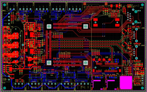
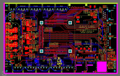
The printed circuit board of the master is made in the same dimensions of the IMD, so that they can be stacked on top of each other, to keep everything as compact as possible. This made for a big challenge to get all electronics parts of the master placed. The master PCB is also one of the few PCBs where high voltage and low voltage are present on the same board. This requires a separation according to the rules, and a galvanic separation one the communication lines from the high voltage side to the low voltage side.

Figure 6: Battery Master PCB

On the master there is also an extra stripped-down slave circuit installed, like those of the actual slave systems on the modules. This stripped-down slave system delivers some advantages regarding the communication between the master and the slave modules. But it is also used to measure the total current of the battery, and the total voltage. A connection is made to a small separate pcb where a resistor divider and a current clamp can be found. In this way the power of the car can be monitored, and with this information the ECU can drive the car in such a way that the regulated power limit of 80kW never gets passed.

Figure 7: Battery power meter

Fire extinguisher

The battery management system, together with all the other safety features in the car, makes sure everything keeps running safe and smooth. But nevertheless lithium-ion batteries will always be a safety risk, because they’re highly flammable. For that reason, a special fire extinguisher is installed inside the battery, this fire extinguisher generates aerosol that can suppress the fire. This fire extinguisher is specially made to put out lithium battery fires, because they are hard to stop with conventional extinguishing methods.

Figure 8: Battery Fire extinguisher

Conclusion

In an electric Formula Student car, safety is a big concern. Not only the lithium battery has to be managed, but also the high voltages need to be controlled so that the car can be operated safely. Thanks to the support of Euroxircuits we have all the resources we need to build these safety systems, and make sure that the user of the car can operate it without risk. Thanks to the great quality of PCBs, the technical inspection of the car went smoothly, and we were able to build a very reliable car.

Formula Electric Belgium LOGOYentl Frickx, Head of Electronics 2018 – 2019

Formula Electric Belgium | www.formulaelectric.be

Diestsesteenweg 692 | 3010 Kessel-lo | tel. +32 (0) 492.80.24.02 | yentl.frickx@formulaelectric.be


Be the first to read all about our news and novelties. Follow us on linkedin-logo google-plus-icon fb-logo Twitter_Icon youtube-logo-full-color


Formula Electric Belgium – Safety Indicators

$
0
0

Introduction

In an electric race car, it is very important to have some systems to indicate to track marshals whether the car is safe to handle or not. Usually this system is a light which can be found on a high point on the chassis. If the light is green, the car is safe to handle, if it is red/orange the car might be still on a high voltage potential.

Figure 1: Indicator light on an F1 car

In Formula Student this is no different. According to the rules you must install a TSAL (tractive system active light) in the top of the roll hoop. This light will be green when the car is turned on, but the high voltage system is turned off. And will blink red when a voltage higher then 60 V is present on the high voltage bus, or when one of the accumulator insulation relays is switched on.

Figure 2: TSAL light on a Formula Student Car

TSAL system

The TSAL system exist out of two parts, with one PCB for each part. There is the TSAL light itself, and there is the board that drives the light.

The Light itself is a double-sided PCB that holds three RGB high power leds on each side. In total the leds can consume up to 5.5 Watts, and unfortunately not all this energy goes into light energy. The compact design made it challenging to cool the leds enough, to keep them at reasonable temperatures.

Figure 3: TSAL-light PCB

To keep the PCB from overheating, two heat pads where added so that a thermal connection can be made to the roll hoop. Thermal via’s where then required to make sure that the PCB heated up uniformly. So that as much heat as possible could be transferred to the roll hoop. In this way we where able to keep the temperatures of the leds below 100 ˚C.

To drive the TSAL light, a separate driver board was designed. This board is a pure hardware logic, because the use of a microcontroller would introduce the possibility of software errors. This is also one of the few PCBs in the car that has both high voltage and low voltage present at the same board. Due to safety reasons, and required by the rules of Formula Student, high voltage and low voltage must be isolated from each other. And when the two are present on the same board, a minimum spacing is required.

Figure 4: TSAL-Driver PCB

The TSAL driver board compares two signals, to decide which color the TSAL must have. There is a signal coming from the battery, which indicates whether all insulation relays are open or not. On the other hand, the driver board measures the voltage on the DC bus, to indicate any voltage higher then 60V. These two signals are compared with each other and drive activate the correct light. The power stage of the lights are two led drivers that can supply a continuous current to the leds, to provide an as efficient possible system.

Figure 5: TSAL-Driver overview

Another extra feature available on the TSAL driver board is a system to discharge the high voltage system of the car. This is needed because the high voltage bus has a very large capacity, needed to provide the motors with a very stable supply. When the relays of the battery are opened, it can take up to one hour for the voltage to drop below 60V. While it is a requirement that the voltage drops under 60V within 5 seconds. The discharge system makes sure this requirement is met. The system is also driven with a signal coming from the battery that indicated the position of the relays. When the relays are all open, the discharge system is activated. Which dissipates the remaining energy from the high voltage capacitors in a power resistor.

Figure 6: Discharge system

Battery voltage indicator

In the Formula Student competition, there is an extra voltage indicator on the battery. This is required because the battery is charged outside the car. This voltage indicator is activated when the voltage on the output of the battery is larger then 60V. But an important extra requirement of this indicator is that it needs to be supplied by the high voltage system itself. In other words, the led should go on when 60V is applied to the circuit, without it having an external supply. But it should also survive 600V. Which results in some demanding circuitry.

Figure 7: Battery HV-indicator light

Because the light must be supplied with the high voltage circuit, there are two solutions for this system. One is to use a resistor divider with a Zener diode, but this would result in a very large heat dissipation at 600V. The other is to build a small power supply.

For our solution we opted for a fly back DCDC converter to provide the system with the required voltage to operate, without too much heat losses. The largest challenge in designing this fly back circuit is that the system must be working between 60V and 600V. Which in it’s turn requires a rather special control chip, and a very specific transformer. On top of that, the board needs to be compact, and routing should be executed with care, to make sure that the supply doesn’t get disrupted by its own switching noise.

Figure 8: Voltage indicator PCB

Conclusion

The safety systems in Formula Student are very important and make sure that students can work safely on this project. Thanks to Eurocircuits, our team (Formula Electric Belgium) had the needed resources to build this safety critical systems, and drive the car (Umicore Pulse) safely on events, while passing the technical inspection without any problems.

Formula Electric Belgium LOGOYentl Frickx, Head of Electronics 2018 – 2019

Formula Electric Belgium | www.formulaelectric.be

Diestsesteenweg 692 | 3010 Kessel-lo | tel. +32 (0) 492.80.24.02 | yentl.frickx@formulaelectric.be


Be the first to read all about our news and novelties. Follow us on linkedin-logo google-plus-icon fb-logo Twitter_Icon youtube-logo-full-color

swissloop – pod Mujinga with Eurocircuits PCBs inside

$
0
0

This years pod, Mujinga, contains three different Eurocircuits PCBs

First of all, we designed a circuit needed for our network communication. It processed the input data of the microcontroller and directed it further to the wireless radio.

Next we had Eurocircuits produce a PCB for our brakes. We had two independent braking systems, including two solenoid valves each. To be able to brake properly, we designed a switching circuit based on a logical input for each valve and printed it on a board in a compact format, which was able to withstand the peak currents of the valves and also very robust. Our hydraulic braking system was able to decelerate our pod with more than 5g.

For reaching high speeds, we needed a high power energy source, which in our case was a self made 10 kWh battery consisting of a 180S3P configuration of LiCoO2 chemistry cells. This pack was able to deliver us a peak power of 500 kW.

To ensure a safe operation we use a BMS measuring all the cell voltages and temperatures. To route the voltage and temperature sensing lines to the slave modules of our Battery Management System, we used custom PCBs produced and partly assembled by Eurocircuits, which were screwed onto the busbar connections between to cells.

Since the cells could not operate inside a low pressure environment, we had to build a pressurized containing the packs and the monitoring electronics. To be able to nicely route the data lines from the BMS to our microcontroller, we made a PCB which got mounted on the feedthrough of the enclosure.

.

Gabriela Fernandes, Business Lead

swissloop | ETH Zürich, LEO B 9.1 | Leonhardstrasse 27 | 8092 Zürich | Switzerland
+41 79 958 41 85 | gabriela.fernandes@swissloop.ch | www.swissloop.ch


Be the first to read all about our news and novelties. Follow us on linkedin-logo google-plus-icon fb-logo Twitter_Icon youtube-logo-full-color

swissloop – The pod Mujinga & Team

$
0
0

THE HYPERLOOP CONCEPT

In 2013, Elon Musk introduced the concept of Hyperloop – a novel, high-speed ground transport system. This mode of transportation projects to levitate passenger and cargo in so-called “pods” in near-vacuum tubes at speeds of up to 1,200 km/h. The realization of Hyperloop redefines the barriers of time and distance. The vision is to revolutionize the ground transportation system towards a faster, more energy-efficient and environmentally sustainable solution. In order to accelerate the development of functional prototypes, SpaceX announced the third Hyperloop Pod Competition 2018. Swissloop is participating for the second time and aims to build the world’s fastest Pod.

SWISSLOOP – THE FUTURE OF TRANSPORTATION

Swissloop was founded in October 2016 and is trying to in- novate Europe’s transportation landscape by developing the Hyperloop concept into a real-world application. The team consists of 20 students from ETH Zurich and other Swiss Universities, with backgrounds in mechanical and electrical engineering, physics, computer science and industrial design. We are also supported by a network of alumni, advisors and partners from the industry. At the Elon Musk’s SpaceX Hyperloop Pod Competition in LA, Swissloop placed third in 2017 and reached top 10 in 2018 out of over 1000 competitors worldwide.

SWISSLOOP TEAM 2018

PROTOTYPE MUJINGA 2018

.

Gabriela Fernandes, Business Lead

swissloop | ETH Zürich, LEO B 9.1 | Leonhardstrasse 27 | 8092 Zürich | Switzerland
+41 79 958 41 85 | gabriela.fernandes@swissloop.ch | www.swissloop.ch


Be the first to read all about our news and novelties. Follow us on linkedin-logo google-plus-icon fb-logo Twitter_Icon youtube-logo-full-color

Electric Superbike Twente – Eurocircuits boards traveling at high speed.

$
0
0

The Team

Electric Superbike Twente designs, builds and races a fully electric racing motorcycle. The goal is to show how awesome and fast electric transportation can be. 2017-2018 was the very first year for the team, so everything is built from scratch. Most components are designed by in-house by the team. For example: frame, swingarm, battery manager, electric motor, battery pack and ECU. The last one is a great example of efficient PCB design with Eurocircuits PCBs.

Functionality

The ECU (electronic control unit) is the central computer of the Lion-GP. It handles a lot of sensor data, for example coolant and motor temperatures, brake and suspension data, Bluetooth tire pressure or 12V battery status. On top of that, it handles the different driving modes. This makes it possible to turn on and off regenerative braking, or adjust the mapping from throttle to torque output. Also, it communicates with all the other electronic equipment, such as the BMS, charger, datalogger and inverter. Finally, it handles all data and registers for the inverter as well.

The PCB

This is a lot of functionality, but in racing it has to be packed as light and small as possible. Therefore, a six-layer PCB layout is made. Fun fact: it has the Bluetooth antenna integrated in the PCB. The outline of the PCB is made exactly to the dimensions of the box it will ride in. This includes the PCB mounted connector and mechanical holes for mounting. To keep the PCB as small as possible, components are placed at both top and bottom.

The result

The box with the ECU is mounted in the nose of the superbike. All the data is processed to the display and datalogger. This year, the design has contributed to multiple wins in the MotoE-competition.

We would like to thank Eurocircuits for supporting our team with PCBs which sit in the heart of our Electric Superbike.

Jeroen Goudswaard, Powertrain manager, Electric Superbike from the University of Twente

Electric Superbike TwenteAuke Vleerstraat 3b, 7521 PE Enschede, The Netherlands

Be the first to read all about our news and novelties.  linkedin-logo google-plus-icon fb-logo Twitter_Icon youtube-logo-full-color

First Think, Then Act, Leads to “right first time”! – seminar

$
0
0
PCB Services | eC Solutions

World of Electronics – Design and Manufacture reliable electronics !

WoTS is more than just an exhibition. Every morning there are various interesting seminars. Thursday morning October 4th, Eurocircuits supports the seminar “design and manufacture reliable electronics” with a lecture.

Our presentation presents the well known principle of “First Think, Then Act. We believe that this will lead to doing things “right first time”. We all have to close the gap between design and manufacturing and thus transforming CAD-data into correct and feasible CAM-production data.

To be able to do this designers need to consult manufacturing companies in an early phase during the design process to define manufacturable specifications for their board. Some manufacturers call this early involvement and consult customers on a personal basis. At Eurocircuits we support our customers with our eC Smart Tools which offer efficient DRC and DFM functionality. Using these tools before starting the actual layout of the board will lead to the “Optimum Design Flow” and doing things “Right First Time”.

Do Register Free here select the seminar of your choice.

Do you wish to know more about the seminar “Design and Manufacture reliable electronics” than read the information on this page on the WoTS website

Eurocircuits TV made a short movie on how Eurocircuits sees “right first time“.

Eurocircuits TV also made movies of every step of the creation process of the PROXIMO exhibition gadget of the World of Electronics. VLOGs click here.

The only procedure to obtain the PROXIMO is to register for the exhibition World of Electronics and to physically collect the gadget at the exhibition.

Do Register Free here and collect your PROXIMO in Utrecht from the 2nd of October till the 5th.

You can find Eurocircuits at the World of Electronics on Booth 11F030. Come and say hello and let us tell you all about Eurocircuits, our PCB and PCBA services and many free to use powerful tools. The Eurocircuits online customer suit offers you the best guarantee to receive your Printed Circuit Board Assembled prototype or small series, “right first time” and in time and within budget.

The Eurocircuits Team will be happy to meet you there.


Viewing all 617 articles
Browse latest View live